10G/25G Fiber Backhaul: Planning GTX/GTH Line Rate and UDP Offload
When multiple high-speed ADCs, radar beams or video streams come together, copper cables top out after a few meters and PCIe cannot leave the chassis. The right backhaul is to drive SFP+/QSFP directly from the FPGA’s GTX/GTH transceivers, offload the MAC and IP/UDP stack on-chip, and send only the payload over fiber at line rate. This article works out the 10G/25G line rate, UDP payload, link budget and the FPGA’s internal division of labor.
1. Why High-Speed Data Needs Fiber Backhaul
Inside the board you use PCIe, and short board-to-board links use copper, but once acquisition nodes are distributed, the distance exceeds a few meters and each channel runs several Gb/s or more, copper and the backplane hit their ceiling first:
1. Distance ceiling: a DAC cable at 10G usually supports only 3–5 m, and active copper is limited too; single-mode fiber with an optical module easily reaches 10 km, suiting distributed acquisition arrays and remote radar fronts.
2. Bandwidth ceiling: a single 1080p60, multi-channel SDR IF, or merged radar IQ often exceeds 10 Gb/s; gigabit copper and backplanes cannot carry it, so you need SFP+ (10G) or QSFP28 (25G/100G).
3. Timing and noise immunity: in noisy industrial environments, fiber provides electrical isolation, immunity to crosstalk and ground loops, and more stable common timing across nodes.
The typical pattern: a remote acquisition card only does ADC sampling and preprocessing, packages results and sends them over one fiber to a central server, which does not process channels individually but only receives the aggregated stream. Here the link line rate and protocol overhead directly decide how many nodes can be attached.
2. 10G/25G Line Rate and UDP Payload Budget (Compute Payload First)
Many treat a “10 Gb/s port” as usable bandwidth, but what reaches the application layer is the payload after encoding, inter-frame gap and protocol headers. Start from how the line rate arises:
| Item | 10G (SFP+) | 25G (QSFP28) | Note |
|---|---|---|---|
| Nominal Ethernet rate | 10.0 Gb/s | 25.0 Gb/s | Effective MAC rate |
| 64b/66b encoded line rate | 10 × 66/64 = <span class=”hl”>10.3125 Gb/s</span> | 25 × 66/64 = <span class=”hl”>25.78125 Gb/s</span> | Actual bit rate on the wire |
| MTU 1500 frame overhead | Preamble/SFD 8B + gap 12B + Eth 14B + IP 20B + UDP 8B | Same | ~62B non-payload per frame |
| UDP payload ratio | 1500/(1500+62) = <span class=”hl”>96.03%</span> | ≈96.03% | Excludes app-layer retransmission |
| UDP payload rate (MTU1500) | 10 × 96.03% ≈ <span class=”hl”>9.60 Gb/s</span> | 25 × 96.03% ≈ <span class=”hl”>24.0 Gb/s</span> | What the app layer actually receives |
| Jumbo Frame (9000B) ratio | 9000/9062 = 99.32% | 99.32% | Raises payload to ~9.93 / ~24.8 Gb/s |
Key conclusion: over MTU1500 UDP, a 10G port delivers only about 9.6 Gb/s to the app, not 10 Gb/s. Size nodes on payload: if each node sends 2 Gb/s of effective data, one 10G link holds about 4–5 nodes (9.6 / 2, with margin), not a full 5. To approach line rate, enable Jumbo Frame to amortize the per-frame fixed overhead.
BER and Link Budget
A fiber link is not done once plugged in; first compute the optical power budget: transmit power − receiver sensitivity = link margin, from which you deduct fiber attenuation (single-mode 1310 nm ≈ 0.35 dB/km) and splice/connector loss (~0.5 dB per connector). SR multimode 850 nm is limited by distance and OM3/OM4; LR single-mode 1310 nm reaches 10 km. A compliant link targets BER better than 1e-12; 25G commonly adds RS-FEC forward error correction, correcting raw ~1e-5 errors to 1e-15, so include the FEC coding gain in the budget.
3. How the FPGA Divides the Work
1. GTX/GTH Transceivers Drive the Optical Module
Series-7 GTX tops out at 10.3125 Gb/s, matching SFP+ 10G; UltraScale/UltraScale+ GTH/GTY run above 16G and support 25G. The transceiver handles serialization/deserialization, 8b/10b or 64b/66b encoding and clock recovery; externally only the high-speed pairs and module I2C management (DDM readout) remain.
2. MAC and Frame Processing
Above the transceiver sits the 10G/25G Ethernet MAC: frame delimiting, CRC check, PAUSE flow control. Rx drops CRC-bad frames and filters by destination MAC; Tx encapsulates frames and fills gaps. This layer is a deterministic pipeline suited to full hardware.
3. UDP Offload Engine
Letting the CPU packetize IP/UDP per frame becomes a bottleneck at 10G. On-chip offload: hardware fills source/dest IP, ports and checksum; the user only writes payload into the DMA buffer, and the engine adds Eth/IP/UDP headers, computes the checksum and fragments by MTU. The CPU does not packetize, only configures the address table once at init — this is protocol-stack offload.
4. Error Statistics and Link Monitoring
On-chip counters tally CRC errors, dropped frames and FEC corrections, reported periodically over the management channel; module DDM of Tx power, Rx optical power and temperature are also collected, alerting early when margin drops instead of waiting for a broken image.
4. Engineering Case: Multi-Node Acquisition Backhauled Over 10G Fiber
A distributed acquisition system has 4 remote nodes; each merges two SDR IF channels and one video channel for ~2.2 Gb/s effective backhaul; the center aggregates over one 10G fiber, and with Jumbo Frame the payload is ~9.9 Gb/s, so 4 nodes totaling 8.8 Gb/s leave margin. All protocols are UDP-offloaded in the FPGA; the host only receives payload.
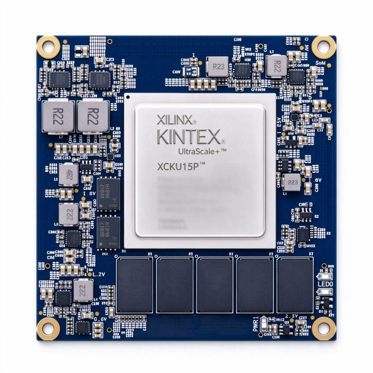
- High-bandwidth link (XCKU15P / Kintex UltraScale+): generous GTY transceiver headroom for 25G or multiple 10G lanes, suited to a main aggregation node that may scale to 25G/100G.
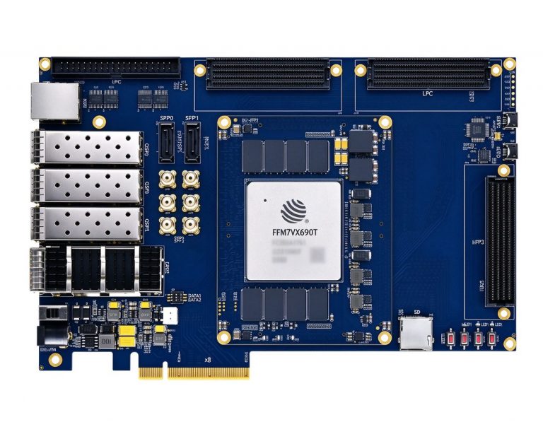
- High-capacity aggregation (DUF7690T / JFM7VX690T): ample logic and on-chip RAM for multiple MACs, UDP offload engines and large queues, suited to central multi-node aggregation and line-rate forwarding.
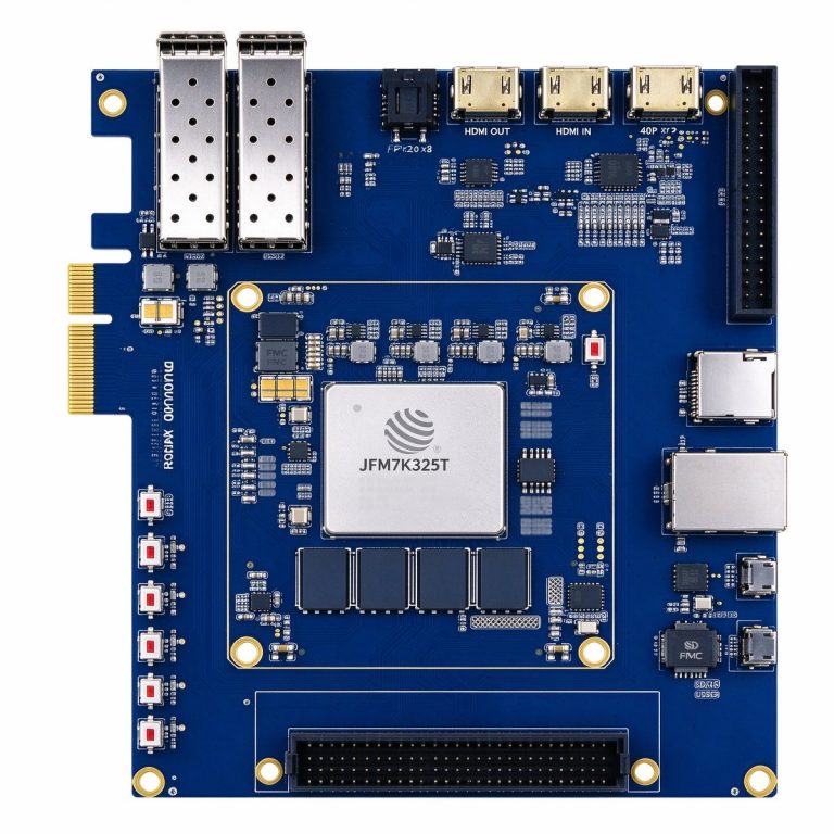
- 10G prototype entry (DUK7325T / JFM7K325T): Series-7 GTX saturates 10G line rate with balanced cost, suited to single-node 10G prototype and entry products.
Fiber backhaul is essentially letting the FPGA’s transceivers and hardware stack finish “sending at line rate” on the CPU’s behalf. Keep two numbers: over MTU1500, 10G delivers ~9.6 Gb/s and 25G ~24 Gb/s of payload. Size nodes on payload rather than nominal rate, compute link budget and BER up front, and the backhaul will not drop speed in the field.