Medical Ultrasound Beamforming: 128-Channel Signal Chain and Data-Rate Budget
A 128-channel color ultrasound probe samples each channel with a 12-bit, 40 MS/s ADC, giving a raw data rate of about 7.7 GB/s — a level a CPU cannot absorb, let alone image in real time. The right approach is to run beamforming, envelope detection and downsampling inside the FPGA first, and only hand the compressed imaging data to the host. This article breaks the 128-channel chain into stages, budgets the data rate at each step, and explains exactly what the FPGA does in between.
1. The Full Ultrasound Imaging Signal Chain
From the probe array to the grayscale image on screen, the signal travels a long chain, with the FPGA sitting after the analog front-end and before host imaging:
1. Probe array (128 elements): emits ultrasound and receives tissue echoes; each element maps to one independent channel.
2. Analog front-end (AFE): TGC time-gain compensation → band-pass filter → variable-gain amplification → ADC digitization.
3. FPGA beamforming: per-channel programmable delay, weighting and summation into a scan line, completing dynamic focusing.
4. IQ demodulation + downsampling + envelope detection: compress the high-frequency RF signal into amplitude grayscale data.
5. Scan conversion + frame buffer + PCIe upload: convert polar scan lines to Cartesian, and send to the host for DSC and color mapping.
The reason steps 3 and 4 must run on the FPGA is straightforward: 128 channels must be aligned, delayed and weighted-summed in microseconds, with each delay changing dynamically with depth. This is highly parallelized, per-channel, deterministic-timing work; software on a general-purpose CPU lacks both the parallelism and the real-time frame rate.
2. 128-Channel Data-Rate Budget (Calculate Before Connecting)
The budget starts from the single-channel ADC and multiplies upward. Take a 12-bit, 40 MS/s ADC:
| Stage | Per-channel rate | 128 channels total | Note |
|---|---|---|---|
| ADC raw sampling | 12 bit × 40 MS/s = 480 Mb/s (60 MB/s) | 128 × 480 = 61440 Mb/s ≈ 61.4 Gb/s (7.68 GB/s) | Raw peak entering the FPGA |
| Beamforming (delayed sum) | 128 channels weighted-summed → 1 scan line | No longer 128 parallel paths after summation | Parallelism is compressed here |
| IQ demod + CIC/FIR downsample | RF 40 MS/s → ~10 MS/s complex equivalent | Single path ~20 MB/s (complex 12-bit) | Below 1/4 of raw after decimation |
| Envelope detection + log compression | 8-bit amplitude, ~10 MS/s | Single path ~10 MB/s | Dynamic range compressed to 40–60 dB |
| PCIe upload to host | — | 256 lines × 60 fps × 8 bit ≈ 122 MB/s | CPU only handles this level |
Key conclusion: compression happens inside the FPGA. What enters the FPGA is a 61.4 Gb/s raw parallel stream; what leaves it for the host is only about 122 MB/s of grayscale frame data. The compression ratio exceeds 60×, achieved by beamforming merging 128 paths into one, then downsampling and detection collapsing high-frequency RF into an amplitude envelope. Skip the FPGA and push the 7.68 GB/s raw stream to a CPU, and neither memory bandwidth nor PCIe can handle it.
Frame Rate vs Number of Scan Lines
In beamforming, every scan line requires a fresh 128-channel delayed sum. Let a frame hold N lines at frame rate F; the FPGA must complete N×F sums per second. With N=256 and F=60 fps, that is 256 × 60 = 15360 scan lines per second, each summing 128 weighted, delayed samples — the starting point for sizing FPGA multipliers (DSP) and on-chip RAM (delay-line FIFOs).
3. How the FPGA Internal Chain Is Divided
1. Synchronized Acquisition and Channel Alignment
The 128 channels usually span several AFEs entering the FPGA over JESD204B or parallel LVDS. The first gate is skew compensation: trace lengths differ per channel, so samples must align to one clock reference before the FIFO; otherwise delayed summation phase-misaligns, producing side lobes and ghost artifacts.
2. Dynamic Focus Delayed-and-Sum
Each element sits at a different distance to the focus point, so echoes arrive at different times. The FPGA compensates this time difference per channel with programmable delay lines (depth-adjustable FIFOs or tapped delays), then multiplies by an apodization weight and sums. Focus depth moves with the time gate, so delay parameters refresh per segment; this consumes large on-chip BRAM and DSP for multiply-accumulate.
3. IQ Demodulation, Downsampling and Envelope Detection
The summed RF line first goes through quadrature demodulation (I/Q mixing), then a CIC + FIR cascade decimates the sample rate; a Hilbert transform finds the envelope, and log compression maps the large dynamic range to 8-bit grayscale. This stage is typical pipeline filtering — high DSP utilization but low parallelism.
4. Scan Conversion, Frame Buffer and Upload
Polar fan-shaped scan lines are resampled into Cartesian rectangular pixels, written to a DDR3/4 frame buffer, then the DMA sends the whole frame over PCIe to the host. This stage cares about DDR read/write bandwidth and the DMA engine, not DSP throughput.
4. Engineering Case: Portable Color Ultrasound Front-End Sizing
A portable color ultrasound front-end uses a 128-channel AFE sampling RF at 40 MS/s, 12-bit. Beamforming must process 128 delay lines and weighted multiplies in parallel, plus a blood-flow Doppler channel. Per the budget above, the raw 61.4 Gb/s compresses inside the FPGA to about 122 MB/s of grayscale frames; a PCIe Gen2 x4 net bandwidth carries it comfortably.
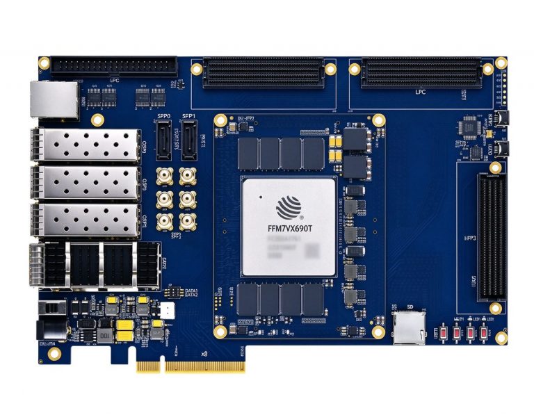
- High-capacity (DUF7690T / JFM7VX690T): ample logic and on-chip RAM to hold 128 delay-line FIFOs, grayscale synthesis and the Doppler channel at once; suited to a full 128-channel, high-frame-rate design.
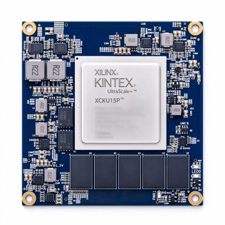
- High-channel expansion (XCKU15P): strong transceivers and multi-channel LVDS aggregation; suited to further channel expansion or distributed probes that send AFE data back over fiber.
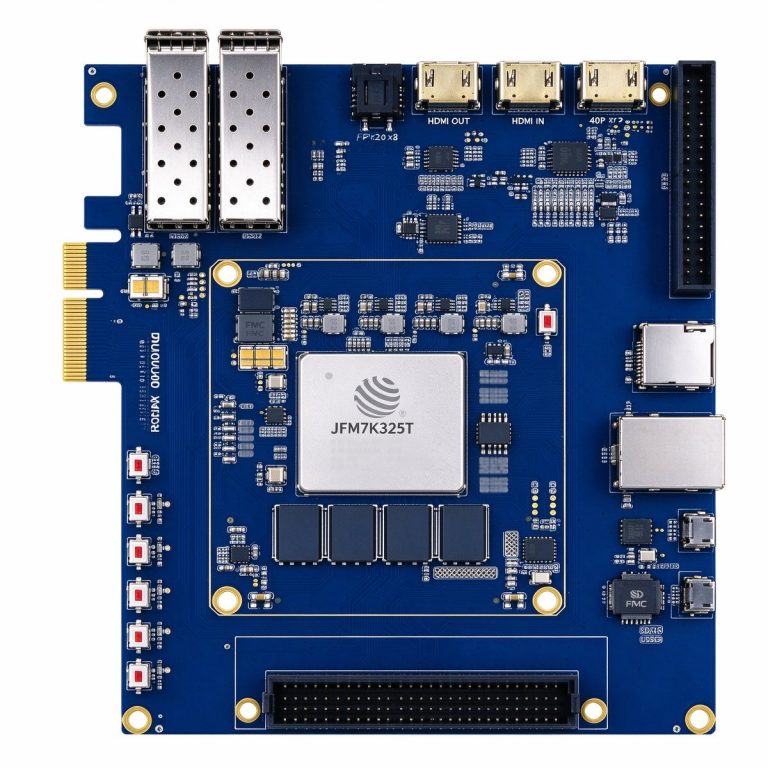
- Mid-range entry (DUK7325T / JFM7K325T): balanced resources and cost; suited to 64–128 channel grayscale prototyping and mid-to-low-end products — run the delayed-sum and detection chain here before moving to a high-capacity platform.
Ultrasound imaging is, at its core, using parallel delayed-and-sum inside the FPGA to turn 128 high-speed raw echoes into a single scan line. Once the data-rate budget is clear — 61.4 Gb/s front-end, 122 MB/s upload — you know which step must stay on-chip and which can go to the host. In medical ultrasound the FPGA is not an accelerator card; it is the imaging itself.