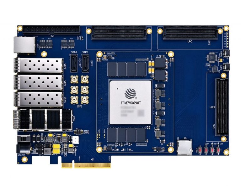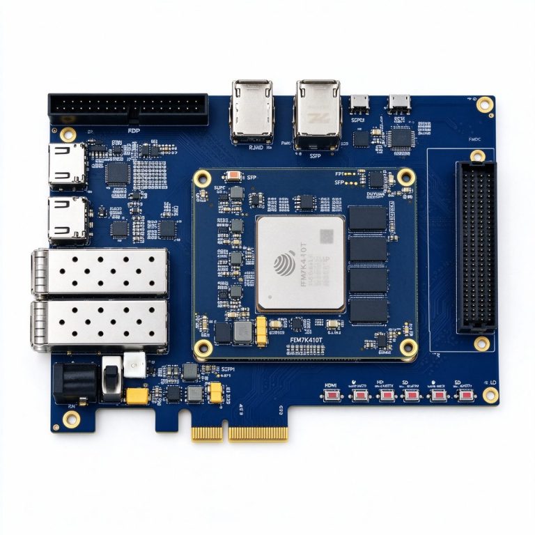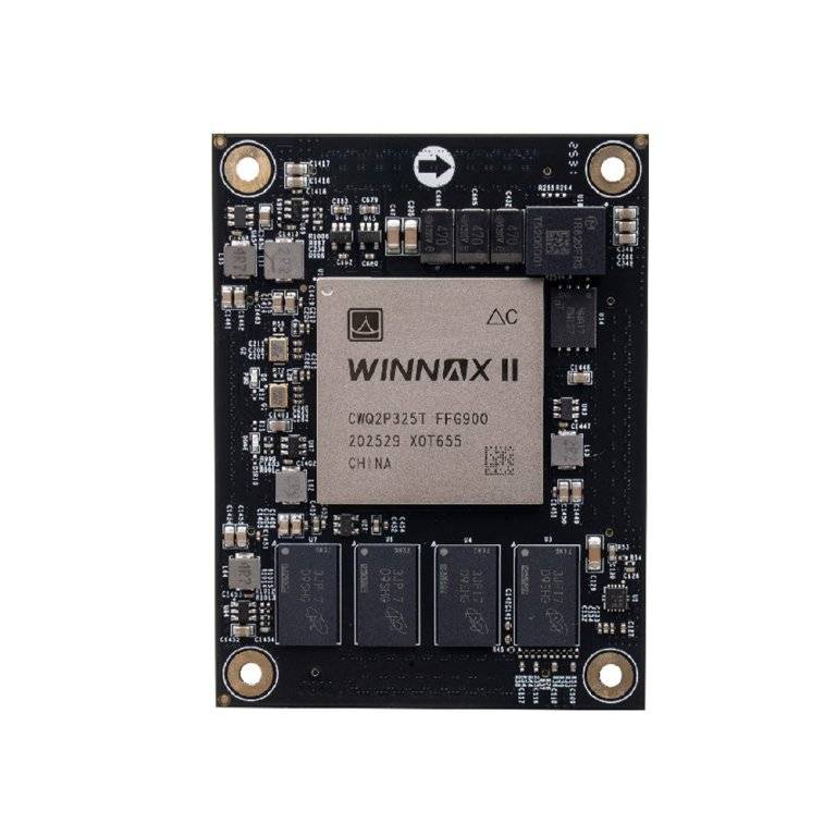
Industrial FPGA Board Reliability: Temperature, Vibration, and EMC Design
An FPGA board that runs fine in the lab crashes on the factory floor — temperature drifts, connectors loosen, EMC fails. Industrial-grade FPGA boards must operate reliably from -40°C to 85°C, survive 5g vibration, and pass IEC 61000 EMC tests. This article breaks down thermal gradient design, vibration reinforcement, EMC shielding, and how to pick a board that actually survives deployment.
1. Commercial vs Industrial: The Real Gap
The same FPGA silicon can cost 2–3x more in industrial-grade version, and the difference is not just temperature range:
| Spec | Commercial | Industrial | Automotive |
|---|---|---|---|
| Operating temp | 0°C ~ 70°C | -40°C ~ 85°C | -40°C ~ 105°C |
| Storage temp | -40°C ~ 85°C | -55°C ~ 125°C | -55°C ~ 150°C |
| Vibration (sine) | N/A | 5g / 10–2000 Hz | 10g / 10–2000 Hz |
| EMC standard | N/A | IEC 61000-6-2/6-4 | ISO 11452 / CISPR 25 |
| FIT rate | ~100 | ~30 | ~10 |
| Typical life | 3–5 years | 10–15 years | 15+ years |
The core gaps: solder ball fatigue under thermal cycling, connector loosening under vibration, and register upsets under EMC — these are the top three field failure causes.
2. Thermal Design: Temperature Gradients Kill Boards
A fully loaded FPGA can hit 100°C+ junction temperature, while the PCB edge may sit at 50°C. A 25°C gradient creates thermal stress that cycles thousands of times and cracks solder joints.
Thermal Design Tips
- Junction temp estimate: Tj = Ta + P × θja. XCKU15P at 15W, θja = 3.5°C/W, Ta = 85°C → Tj = 85 + 15×3.5 = 137.5°C, exceeding the 100°C limit — heatsink or forced airflow is mandatory.
- PCB thermal balance: Pour copper ground under the FPGA, add thermal vias (0.3mm diameter, 1.5mm pitch) around the perimeter to conduct heat to the bottom layer.
- Temperature sensor: Onboard NTC thermistor, read by the FPGA, auto-throttle or alarm above 95°C.
- Power sequencing: Core voltage (1.0V) before IO voltage (1.8V/3.3V) to avoid latch-up.
Real Case: Industrial Camera Crashes in the Field
A customer used a commercial-grade Kintex-7 board for machine vision. It ran fine at 25°C in the lab for a week, but crashed 2–3 times per day once installed in a 60°C control cabinet. Cause: FPGA junction temp hit 95°C, exceeding the commercial 85°C limit; thermal cycling occasionally corrupted the configuration SPI Flash. Switching to industrial-grade silicon plus a heatsink solved the problem.
3. Vibration and Mechanical Reinforcement
Industrial environments (machine tools, robotics, automotive) are harsh on connectors and BGA solder balls.
Vibration Hardening
- Underfill: Dispense underfill epoxy under the BGA package to prevent solder ball fatigue under thermal cycling.
- Connector selection: Use latching connectors, not friction-fit; add mounting brackets for FMC mezzanines to prevent vibration-induced disconnection.
- Board thickness and mounting: Use 1.6mm+ PCB, four-corner mounting, avoid large unsupported areas.
- Heavy components: Keep capacitors and inductors away from board edges to prevent solder pad fracture under vibration.
4. EMC: Why Your Board Keeps Getting Interfered
IEC 61000 series is the baseline for industrial EMC: ESD ±8kV, EFT ±2kV, Surge ±1kV, Radiated Susceptibility 10V/m.
EMC Design Tips
- Interface filtering: Add common-mode chokes + TVS diodes on every external port (Ethernet, USB, RS232) to protect the FPGA during ESD events.
- Power decoupling: 0.1µF + 10µF capacitors per power pin, placed close to the pin, minimize loop area.
- Shielding cans: Add metal shields over high-frequency clock regions (>100MHz) to contain emissions and prevent external interference.
- Grounding: Connect analog and digital grounds at a single point to prevent digital noise from leaking into ADC front ends.
Seventy percent of industrial FPGA board reliability is decided at the PCB design stage — thermal gradients, vibration hardening, and EMC shielding cannot be retrofitted. When selecting a board, ask: what is the temperature range? Which EMC standards did it pass? Is there a vibration test report?